
The tube and pipe environment has introduced the ability to add custom elbows. It also gives users the ability to turn the end cap on and off. The option to rotate a section view as well as edit, suppress, and delete within a view representation is going to allow for more accurate views, as well as easier ways of saving and storing them. Section views are another area that has been updated both in the Part and Assembly environment. This tool is going to help Inventor users complete their engineering workflow and add extra information for their customers or workshops. These ‘Finish’ properties are then stored in the parameters and can be mapped through to iProperties, and therefore drawings if required. Standards can also be set up in the design data, this will give companies with a consistent manufacturing process more compliance. During this process users will add one or more of the five Finish variables:īy selecting each of these features a different list of properties is then required to be filled in to define the process.

This also works in assembly, sheet metal and weldment environments.

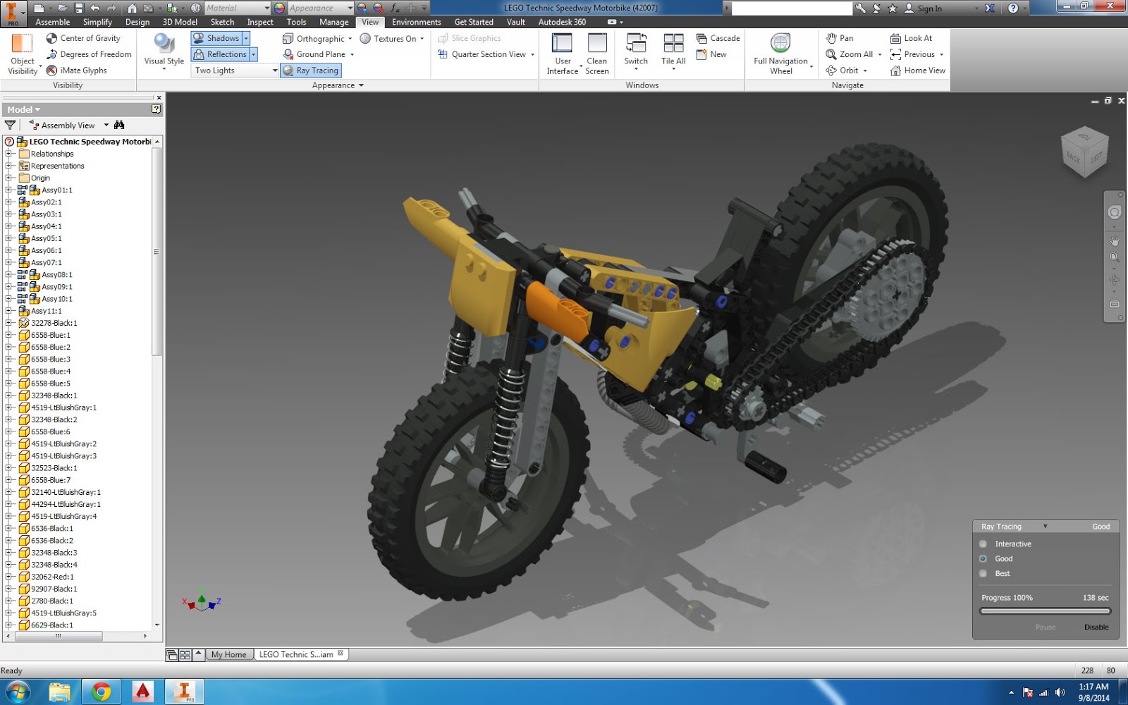
The Finish tool will allow users to add an extra step in the workflow and add the manufacturing process to the component. The new Finish function has been added due to it being a highly requested feature. The part environment is where the majority of new tools for this release are introduced. This allows for sketches to be made clearer depending on the sheet colour. Starting with sketches, and the ability to edit the colour scheme of sketches on a drawing has been introduced. Or, create animations, and output them as video files.The majority of the new tools and features in this update come from customer feedback from the Autodesk Ideas Station. Use snapshot views to create exploded drawing views or raster images of the model. Insert an assembly model and create tweaks, trails, and snapshot views. Use the default template or a custom template to create a presentation file (.ipn). Relationships control component placement and DOF (Degrees of Freedom). Parts and subassemblies are connected by assembly relationships.

And you can easily make changes without having to hunt for the right feature or fight with existing geometry and constraints.Īn Autodesk Inventor assembly model is a collection of parts and subassemblies that function as a single unit. The command you need shows up right at your cursor, right when you need it. Complex geometry is created the way you think…without having to devise workarounds. Inventor eliminates the interruptions that prevent you from making progress. With Inventor you can work efficiently with a powerful blend of parametric, direct, freeform, and rules-based design capabilities. Inventor® CAD software provides professional-grade 3D mechanical design, documentation, and product simulation tools.


 0 kommentar(er)
